Some background
The AS3330 is a dual linear/exponential VCA. The Eurorack module should perform as follows:
- 10Vpp signal inputs
- 10Vpp signal outputs
- Designed to be used with envelope generators or LFOs
- Ranging from 0V-5V, 0V-10V, and 10Vpp CV signals
Datasheet and Digisound 80-9 Circuit Design
Refer to the datasheet diagram which I have drawn for the commentary below. I took some explanations from the Digisound 80-9 module documentation. The Digisound 80-9 has nice explanations on how the 3330 chip works. I’ve used ohms law and voltage divider calculators to make sense of the datasheet electrical characteristics and circuit.
Signal inputs
- pin 4 and 13
- 10Vpp
- A current input
- A summing node
- Uses 100K resistors to convert an input voltage into an input current
- The Digisound 80-9 circuit added compensation resistor and cap. And a diode to prevent latch up problems.
Signal outputs
- pin 1 and 16
- should be 10Vpp
- A current output
- Uses a transimpedance amplifier configuration to convert output current into output voltage
- If the output is lower or higher than 10Vpp I will experiment with the 51K feedback resistor
- Based on the Digisound circuit. The 51K resistor sets the maximum gain to 0.4.
- I used a 100K resistor for the feedback resistor to get the same voltage output from the input.
- Uses a transimpedance amplifier configuration to convert output current into output voltage
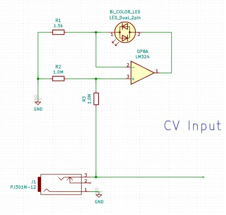
Control voltage inputs
- Linear inputs
- pin 7 and 12
- 0 to 10V based on the datasheet circuit (through the resistor)
- 0V = max attenuation
- 10V = unity gain
- Icl = 100uA at 10V through the 100K resistor
- A current input
- The 100K resistor converts the input voltage into an input current
- A summing node
- Would be able to add more control inputs like AM (Digisound 80-9) through a resistor
- A compensation capacitor connected to the VG pin prevents the log converter from oscillating when the gain of the linear control input is below -80dB (Digisound 80-9)
- 1nF or larger
- The input must be normalled to VCC through a jack in order to use one of the other (linear or exponential). If one is zero, the gain will be zero regardless of the voltage on the other (Digisound 80-9)
- Exponential inputs
- pin 6 and 14
- -1V to 10V based on the datasheet circuit (through the resistor divider)
- 0V = unity gain
- 10V = max attenuation
- A voltage input (unverified)
- A voltage divider brings down the input voltage (33K and 1K).
- @10V, Vce would be 294.12 mV
- A voltage divider brings down the input voltage (33K and 1K).
- Based on the Digisound circuit. The exponential input should be inverted first to increase gain by increasing the control voltage. A 0V input should mute the signal, and a 10V input should be at unity gain. That would give you another summing node so that you can add more control inputs through resistors.
- The input must be normalled to VCC through a jack in order to use one of the other (linear or exponential). If one is zero, the gain will be zero regardless of the voltage on the other (Digisound 80-9)
Gain inputs
- pin 2 and 15
- Based on the datasheet circuit, a resistor is connected to VCC to provide a reference current. A 100uA reference current is implied.
- RB = 150K at +15V
- RB = 120K at +12V
- 100uA produces good scale accuracy (Digisound 80-9)
Distortion trim input
- pin 3 and 17
- I currently don’t see any information on the datasheet. It’s just connected to ground.
- In the Digisound 80-9 documentation, it uses a trimmer. Said to reduce distortion. Feedthrough would be affected though as it was said. I’m not really familiar with feedthrough yet.
IDLE input
- pin 8
- Variable operating characteristics. Class A to Class B.
- A 6.8K resistor would set it to Class AB (datasheet)
- A 68K resistor would set it to Class A (datasheet)
- A 767K resistor would set it to Class B (datasheet)
- Good balance between distortion, bandwidth and control voltage feedthrough (Digisound 80-9)
Power inputs
- VCC+
- Max +18V in relation to GND
- +12V is safe
- VEE-
- Max -6V in relation to GND
- Current limiting resistor required for VEE voltages greater than -6V
- Based on the datasheet
- At -15V with a resistor of 680R, the current would be 22mA
- So for -12V we could aim less than or equal to 22mA (ohms law calculation)
- I think a 560R resistor would be ok (21.4mA)
- Based on the datasheet
- Can use a -5V regulator with no current limiting resistors needed
Resources
- https://electro-music.com/forum/phpbb-files/203_006_vca3330_schematic_119.pdf
- Digisound 80-9
- http://www.geofex.com/Article_Folders/panner.pdf
- https://www.analog.com/media/en/technical-documentation/application-notes/an148fa.pdf
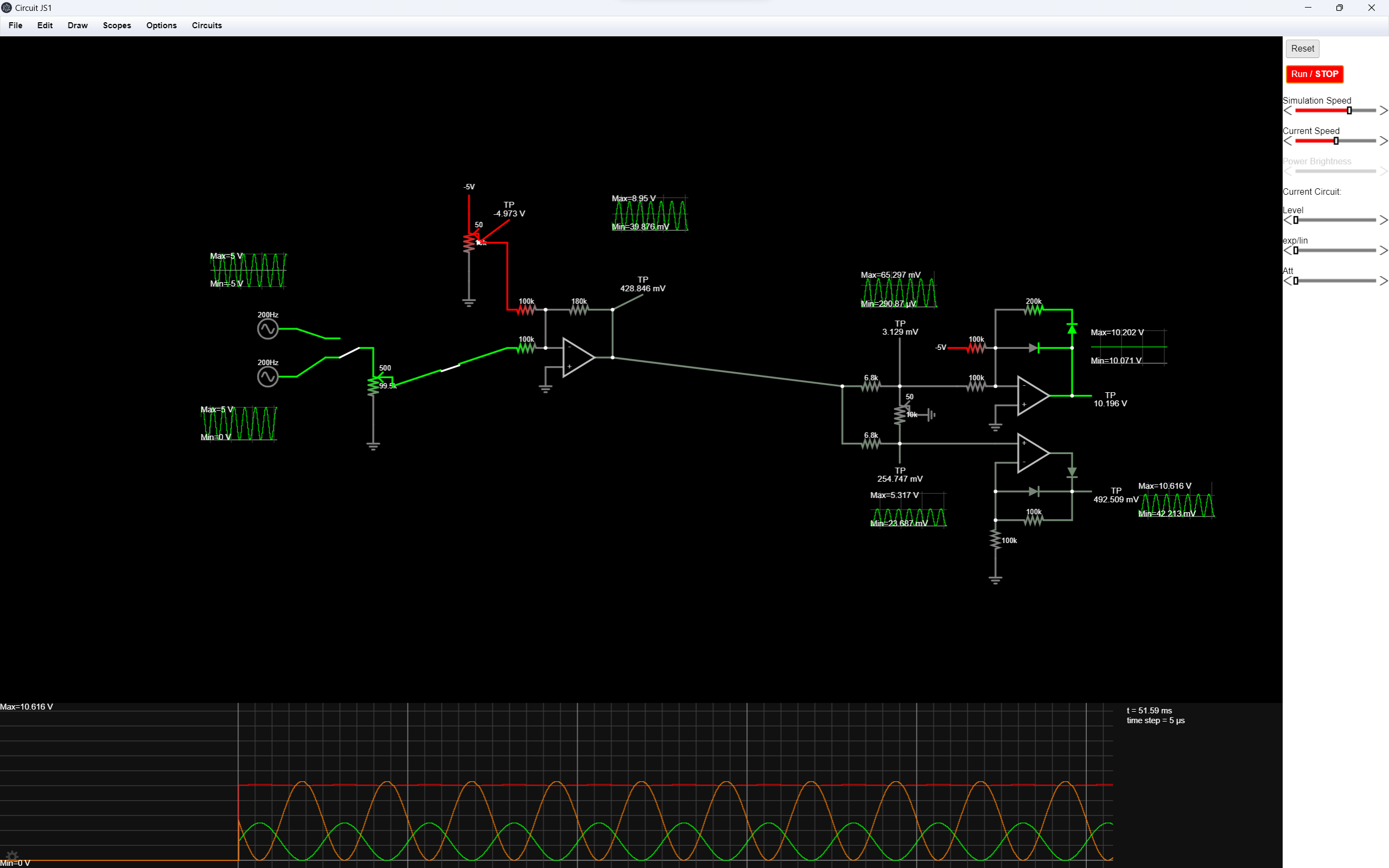
Circuit Design
Design inspiration
I took some inspiration from Intelligel’s Quad VCA module. It features four VCAs that can have a linear or exponential response. Its response can be tuned to anything in between linear and exponential. The level knob controls the CV offset so that you could use a wide range of voltage signals - bipolar or unipolar. The CV input can also be attenuated using a knob.